Zappette The Robot Clock


In the past people have asked me for a schematic for Zappo. I do not have one for Zappo nor do I have one for Zappette. That said below I have tried to link to examples of all the individual circuits/chips I have used and I don't deviate much from those examples.
The MP3 player is also on the main shield (visible with the SD card on top). This time I used a FN-M16P I received directly from Flyron but is more readily available from DFRobot who also provides a great library/tutorial. I found this module way better than the SOMO-14D I used for Zappo. It is way cheaper, uses MP3 formatted files and doesn't require an outside LM386 amplifier. That said I had to write my own randomizing routine to be able to randomly play a folder of MP3 songs. It has a random function but it random plays all folders on the card and I needed separate folders for alarms, sound effects and sounds. One other issue was that two 3W 4-ohm (also tried 8 ohm) speakers at high volume drew more power than the Arduino could handle. The current was too high at high volumes and the poly-fuse on the Arduino would trip and reset. To fix the issue I bypassed the Arduino with a voltage regulator from the 9V wall plug to get 5V for the FN-M16P. At high volume it was pulling around 800ma.
I needed a lot of buttons, switches and PIR inputs for the clock and MP3 player and I quickly exceeded the number of I/O pins of the Arduino UNO ( 14 digital + 5 analog ). I used 2 daisy chained CD4021B chips as described in the Arduino ShiftIn library. This gave me 16 inputs for the cost of only 3 pins on the Arduino. (switch board).
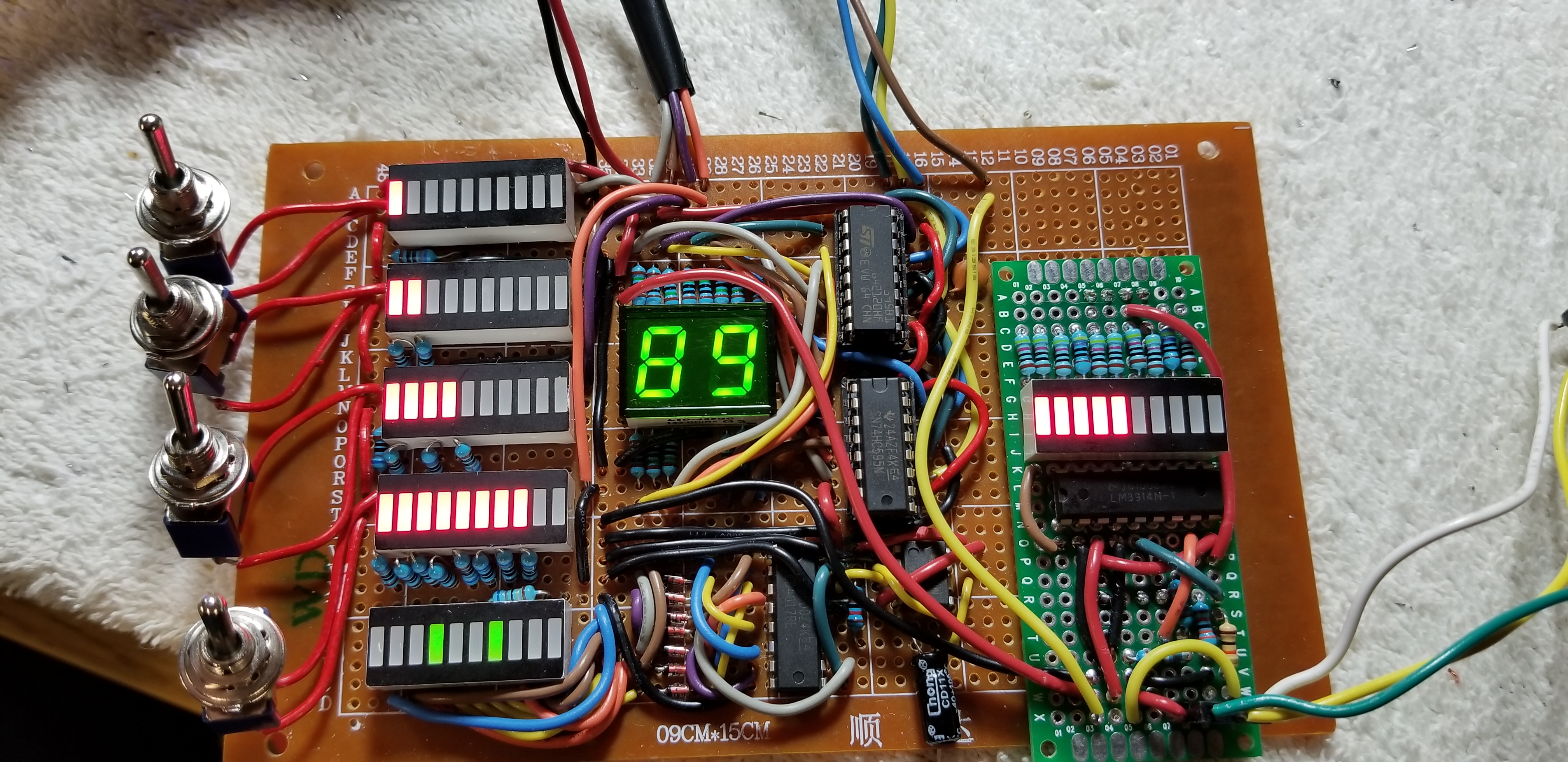
4 of the switches attached to the CD4021B are for the switches on the front panel. These switches are binary bits for controlling which alarm file to play (0 to 15. 0 = random MP3. 1-15 = pre-defined alarm files). They are tied to LED bar graphs to show the value of each bit to help visualize the binary math. In the Arduino these are converted to an Integer which is in turned mapped to pins of the 2 digit 7-segment display on the front panel. I used two 74HC595 chips as described in the Arduino ShiftOut library to draw the segments. This gave me 16 outputs for the cost of only 3 pins of the Arduino. One of the outputs is also used to control a MOSFET that turns on an LED chaser circuit when the alarm is on.
Also on the front panel is a pontentiometer and LED bar graph display for volume. The potentiometer is tied to an analog input of the Arduino which then maps the voltage to an integer between 1 and 30. That integer is then sent to the setVolume() command for the FN-M16P chip. The bar graph uses a LM-3914 bar graph driver to map the voltage to LEDs.
For the time display I used a 7 Segment Backpack from AdaFruit Industries. This was amazingly simple! Like the real-time clock it is I2C based so it required no additional Arduino pins beyond the 2 already being utilized for the the RTC. I added a photoresister to an analog pin of the Arduino which maps to a brightness integer for the display. So as the light dims the 7 segment display (plus eyes and mouth) dims with it.
For the eyes and mouth I used two 8X8 LED Matrix "eyes" and a 16X8 LED Matrix "mouth". Again these are I2C based so they were super simple to use. Code wise the animation was a fun and interesting challenge. I defined bitmaps to be drawn using AdaFruit's library and mapped them into sequences for the animation. This was an interesting and fun challenge. See the code for examples of how to handle a lot of inputs, outputs and animation using millis() instead of delay().
The "ears" are LM-3914 bar graph drivers mapping the speaker output voltage from the MP3 chip to LED bar graphs. I left an exposed potentiometer to be able to adjust the sensitivity.
I added an Ultrasonic Distance Sensor to the front so Zappette could react to someone getting close to it. If something is within 12 inches the eyes go crossed. If it gets within 6 inches and stays there for a few seconds the eyes and mouth get "angry" and a sound plays. The "nose" is a PIR sensor to detect motion. When motion is detected it sends positive voltage to the switch board and causes the eyes to roll like they are searching the room.
I added a thermometer to measure the interal temperature using a 5V gauge I bought off eBay in a 2-pack for a robot halloween costume I made for Cooper. It was laying around and I thought now was a good time to use it. It is right next to an air vent so it should match the room temperature as well.
The antenna on the ears are connected to each other via an EL wire loop. This provides some visual flare and also works as a night light. Because I wasn't sure if Veronica would always like the night light on I added a knife switch to control the 9V power to the EL wire transformer. If the same knife switch is flipped to the opposite side it triggers a MOSFET to switch on 5V to the switch board and forces Zappette to "sleep" by turning off the eyes/mouth and leaving only the alarm clock functions on.
The body is made out of cherry wood finished in a clear gloss lacquer ( not polyurethane ). The neck and legs are a recycled garage door spring (same as Zappo. They just look perfect!). The arms are plastic wire conduit with some brass spray paint and wood I shaped to look like clamps. I added some decorative trim finished in brass to try and give this a more fancy finish than Zappo. I added a heat sink I had laying around to the base because I just thought it looked neat.